Unknown Territory
Also today some appearances still are ´wondrous´. For example it´s an open question whether these machines are a ´perpetuum mobile´. Faraday is known as an outstanding experimental expert and theorist, however that generator-type merely is noticed in official textbooks. So the unipolar-machine still is a ´scientific white spot´. Now here that problem is analyzed exclusive by view of the aether. At picture 09.08.01 schematic is drawn the general principle, upside by longitudinal- and below by cross-sectional view through system axis.
Conductor-Disk instead of Coil
This effect corresponds to the induction-laws: one can imagine the disk existing by many conductor-wires arranged radial. Each ´wire´ crosses the magnetic field. Based on Lenz-rule, a current is generated within the conductor. At a flat conductor, the current runs circling around, building so-called ´vortex-flows´ (WS, ´eddy-currents´, marked by some dotted curves). The magnet-field of induced circling flow by itself hinders the movement of the conductor. So mechanical drive is demanded for running that machine as a DC-generator. Opposite, this principle is used as ´eddy-current-brake´, e.g. at trains, lorries or busses. The ´recovery´ of electric energy via mechanical brake-energy is most important at momentary development of electric cars.
Over-all Magnet-Disk
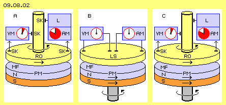
Below is drawn a disk-shaped permanent-magnet (PM) with its south-pole (S, red) and north-pole (N, light blue). The rotor (RO, yellow) is turning at the magnetic-field upside of the north-pole. Again two sliding-contacts (SK) are installed outside at the rotor and inside at the shaft. The voltmeter (VM, dark-red) shows only few voltage. An ammeter (AM, dark-red) however shows strong current, available for a consumer respective load (L, blue).
Low Voltage, strong Current
Common current-generators produce voltage in changing strength and direction. Only by a second step comes up that flowing and finally via commutator results the (pulsating) DC. Opposite, the unipolar-generators immediately produce DC of astonishing high strength at astonishing low voltage. The turning of the rotor demands power-input. However the demanded forces increase not proportional to the load - seemingly contradicting the common understanding of energy-constant. It makes problems to drain-off the current from these machines, e.g. because sliding-contacts produce heat and abrasion. Occasionally were use ´liquid contacts´ (e.g. mercury or molten metal), thus techniques most complex.
Rotating Magnets
The permanent-magnet (PM) is mounted at a shaft. The magnetic field upside of the north-pole is left-turning. Also the shaft should turn left, so both movements add. The conductor-disk (LS, yellow) stands stationary within the rotating magnetic field. Via contacts again are connected a voltmeter and an ammeter - which show no deflections.
Also this result seems to contradict the rules of induction. At scientific discussions diverse explanations for the characteristics of magnetism came up, e.g. no field-lines could exist, the magnetic field could not rotate, mechanical effects could only come up by an electric flow etc. So this variation unfortunately was assumed not usable for generating electric current.
Based on my consideration however well could circulate eddy-currents at the conductor-disk. However these are running concentric around the axis and thus these sliding contacts can not pick up the flow. At the other hand the back-flow of magnetic field from north- to south-pole is not optimal organized. So probably a generated flow could be gathered at the stator - by suitable arranged constructional elements.
One-Part Faraday-Generator
The permanent-magnet (PM) and the rotor (RO) as well are installed at a common shaft. Both are turning likely sense and likely fast within space, so no relative movement between both constructional elements exists. The magnetic field shows no changes during the rotation. Based on valid laws thus no induction should come up. If however previous voltmeter (VM) and ammeter (AM) are connected via sliding contacts, they show a (relative low) voltage and an (unexpected high) strong current, available for a load (L, blue).
Obviously this ´one-part Faraday-Generator´ violates the induction-laws. At all common generators the turning element is affected by a resistance versus the stationary element and the back-affecting force of rotor is supported at the stator. Here however the magnet-disk is fix combined with the conduction-disk, so no mechanical part is given for suspected back-affecting force.
This generator demands draft. The demanded drive-force however is independent from the load taken off the system. So that Faraday-Generator seems also to violate the law of energy-constant. The public discussion thus mainly is searching for an approval of any kind of counteracting force. As this did not succeed satisfactory, the main-physics ignore consequently this problem since many years. However just because basic physical laws are involved, the explanation of these interactions could result new insight.
Without Voltage no Current
What should cause free electrons (without according power impact) to move into a certain direction by vast amounts? How should a charge (existing only at the surface of the conductor) be able to affect force onto electrons (which are located inside of the conductor)? Above this, how should an electric and / or magnetic field be able to produce real effects through the Nothing of the alleged vacuum? These unipolar-machines approve clearly, the common understanding of electro-techniques are insufficient. Already Tesla and e.g. DePalma suspected other factors are involved, e.g. something like the aether (however nobody made up concrete definitions for this substance and the necessary functions).
Usual Construction
At this picture upside right that voltmeter is drawn once more. Now I suppose strong voltage exists indeed, however between the rim of disk and the earth (E). The atoms of permanent-magnet and of the disk are turning within the space. The magnetic flow contributes additional aether-movements. Thus an aura exists around the rotor (which might reach out several meter). These aether-movements have a stroke-component (like at every aether-whirlpool, see previous chapters).
This is equivalent to high charge (HC) and thus a potential exists towards the normal charge (NC) of the grounding. The Free Aether presses down the ´thick charge-layer´ to the level of average charge. This is the usable flow, its strength is measured by an ammeter (AM) and it´s available for a load (L, blue). The strong current of unipolar-generators e.g. is used for welding. At simple welding-method, the plus-pole-clamp is attached to the working-piece, thus practically grounded. The DC of the generator thus needs no back-flow-wire for closed conductor-circuit. Really necessary is only one wire from the disk-rim sliding-contact to the earth. This quite new understanding of processes will become clearer with following constructional variations.
Spoke-Conception
Relative Movement
The usual sliding contacts develop faults. The current collection via molten metals is not practicable. That´s why here the charge-catcher (LF, geen) are stationary constructional elements (of the stator) and reach far into the groove of the rotor (thus are replacing previous sliding contacts). Like sketched at longitudinal view at A, the charge-catcher (LS, green) do not touch the rotor. This picture below at C shows a cross-sectional view at the area of the charge-catcher.
Thrust of Aether
At the rim the charge is accumulated to high layers, building a potential gradient towards the normal charge of the ground. Finally there comes up the necessary ´tension´, causing the electric flow, corresponding to the strength of the current. No ´charge-carriers´ are running through the conductors (only as a second appearance some free electrons are crawling through the wires). No aether is floating through the space. All aether all times keeps its place at the charge-catchers and along all conductors. The rotating masses of rotor and its magnetic fields just pile up some ´aether-turbulences´ at the surface of the charge-catcher, which at the following are lowered and pushed aside by the normal pressure of Free Aether.
Above the charge-catcher remains the same ´aether-volume´ all time . The aether there is whirled-up by the rotor-spoke and magnet-field. At the following gap, the Free Aether eliminates that ´disturbance´. That motion-hill is shifted to regions with thinner charge-layers, thus towards the ground. Because there are no ´charge-carriers´ in shape of electrons, none of must be fed-back. All aether along the charge-catcher and the conductors is only whirled-up some higher and afterward is smoothed-down. At the charge-catchers periodical a ´wave is piled up´, sloshed along the conductor and running-off into the ground.
Many Variations
As an example, seven of these magnets are drawn. During the rotor-revolution, they are moving over six charge-catchers (LF, green). Each magnetic field is ´painting´ turbulent aether-movements at the arch-shaped charge-catchers. Afterward at next gap, the Free Aether flattens that high reaching motion-layer and finally presses-off that charge from the area of the rotor. Naturally diverse magnets and charge-catchers can be installed as one likes it, also several modules aside each other at the shaft. That generator will produce relative steady DC or pulsating DC e.g. by two or three phases.
Simple Model
For a simple functional model some round permanent-magnets will do. In order to achieve closed magnetic flows, each two magnets could be connected by a yoke (dark-grey), like sketched at this picture below left side at C by longitudinal view.
Generator plus Motor
At a common shaft (dark-grey) a generator and a motor are fix installed. Left side at this shaft, previous generator with its simple permanent-magnets is drawn. The charge-catchers (LF, green) are connected by a wire, guiding the current from that high charge (HC, see arrows) to the motor at right side.
Overunity
Professional physicist worry about energy-constant - even no danger exists at all. However that law is valid only within the gapless aether, because only its movements never can got lost (opposite to the ´world of material particles´). Like at fluid-technology, energy exists unlimited, there e.g. in shape of the normal molecular movements. Here infinitive energy exists by the steady narrow ´trembling´ of Free Aether and its pressure versus all wider movements. At least via permanent-magnets the motion-pattern of magnetic fields are available ´for free´. It is ´only´ necessary to organize given movements temporary that kind, a wanted benefit is achieved.
Here a local turbulence is generated by the turning of the rotor combined with the spiral-turning magnetic field-lines. The aura of that ´disturbance´ reaches high above the surface of the charge-catcher. The Free Aether affects pressure, pushing the movements down to likely level - and thus drives that movement-hill - named electric current - into the charge-sink of the earth. No change occurs concerning all movements as a whole (equal to ´energy´). At fluid-technology the skillful organization of flows produce ´overunity´ without any doubts, e.g. at each wing (the curved faces generate relative emptiness and accelerated flow, the difference to normal air pressure represents the lift-force). Analogue here such local and temporary ´disturbances´ are generated, which are transferred into flowing charge respective electric current - by just normal aether-pressure.
The consequent realization of previous proposals could finally approve, if the strange effects of unipolar-machines result the performance of an overunity generator. Common generators produce voltage and flow in changing directions. All aether-movements thus must be delayed and accelerated again into opposite direction. So work-load exists on and on versus the inertia of aether-movements. At previous conception of unipolar-machines all aether-movements are running into same turning sense all times. At the faces of charge-catchers exist only higher and lower vortices, periodical changing, practically only an upward-slosh and falling-back vertical to the surface. The Free Aether is working (for free) like a pump as the high vortices become reduced to normal size and pushed along the conductor. That working-principle well could be economic (i.e. show more benefits than costs).
It was a hard job to develop the idea of that ´golf-club-generator´ at previous chapter. It´s not usual to cut conductor-loops or -coils in two every day. So the description of new functions was somehow difficult. Probably that principle will clear up by a second starting point: replacing the coil by a disk. Michael Faraday started diverse experiments already in 1831, resulting strange effects and finally the famous ´Faraday-Generator´. This machine produces continuous DC without the usual (two-pole-) commutator and thus is also called ´Unipolar-Generator´. Today these devices are also called ´N-Machines´ because they probably show n-fold effect. At the internet many discussions are running around these terms.
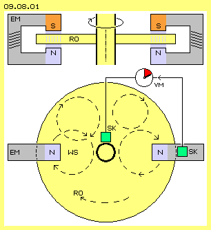 Left and right side are drawn two horseshoe-magnets, each with a south-pole (S, red) and a north-pole (N, blue). Either permanent- or electro-magnets (EM, grey, energized by DC) are usable. A disk-shaped rotor (RO, yellow) is turning within the magnetic field. The rotor is fix mounted at a shaft. The rotor and the shaft are build by electric conducting material. A sliding contact (SK, green) glides along the surfaces of the shaft and a second contact slides along the rim of the disk. The faster the rotor is turning, the stronger is the voltage between both contacts, like shown by a voltmeter (VM, dark red).
The more horseshoe-magnets are used, the more DC that machine produces. At extreme case, the magnets could be installed all around. Already Faraday (and many contemporary researchers) made experiments with disk-shaped permanent-magnets, where the rotor in total was turning within an axial oriented magnetic field. This conception is sketched at picture 09.08.02 left side at A.
 As an ´average citizen´ I only know, normal wall-sockets have 230 V voltage and can take a load of maximum 3500 W because the fuse limits the strength of current to 16 A. In comparison is pretended, even unipolar ´toy-devices´ show voltage of only few mV, nevertheless produce currents of 30 A. Already hundred years ago, machines were build with 300 kW, 500 V and 600 A. Currents for electrolysis-installations usually need only 6 to 40 V however strengths above 6000 A. Up to 300000 A are claimed for machines producing ´military benefits´ - for usual unlimited nonsense.
That´s why machines are preferred, where the conductor is stationary installed at the stator and the magnets of a rotor are turning around the system axis. So relative movements between conductor and magnetic field exists, resulting a current according to induction-laws. This variation is sketched at picture 09.08.01 at the middle at B.
As long as one does not know the causal connections, only the method ´try-and-error´ may help (however I trust in ´think-and-error´ and a score-rate some beyond ´fifty-fifty´). The researchers of century before last had great success with their ´wild´ trying-out new things. Faraday for example did prove a third variation, which is sketched at this picture right side at C.
At previous picture 09.08.02 right side at C, the one-part Faraday-Generator is drawn only schematic. Without any doubt however such machines deliver DC at the rim, although practically no voltage exists between both sliding contacts. Some unipolar-machines produce usable current even of extreme strength. Common understanding can not explain this appearance, because finally a tension U (lat. ungere = push, press, urge) can force movement of the charge-carriers (free electrons or ions) within an electric conductor. Without voltage (thus a work-potential between charges of different strength) no electric flow can come up.
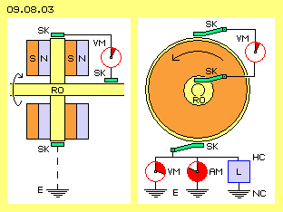 Picture 09.08.03 left side shows a longitudinal cross-sectional view of most used version of unipolar generators. The electric conductor-disk of the rotor (RO, yellow) is fix installed at a shaft. At each side a permanent-magnet is fixed, so the disk is covered by a north-pole (N, blue) and a south-pole (S, red). The magnetic field thus is turning like the disk. A voltmeter (VM) between the sliding contacts (SK, green) at the rim of the disk and at the shaft indicates only few voltage.
The basic principle can be build by diverse constructions. An example is shown at picture 09.08.04, upside at A at first by longitudinal cross-sectional view. The rotor (RO, grey) is build exclusive by iron (FE). A coil (SP, red) is winded within a deep groove, concentric around the axis. For excitation a DC is fed, resulting a torus-shaped magnetic field around the coil, here marked by some dotted curves. So this rotor combines the function of magnet and of conductive disk same time. If that heavy rotor is accelerated to high revolutions, strong kinetic energy is stored (plus intensive aether-movements of internal magnetic flow). If the rotation of that machine abruptly is decelerated (in sense of an eddy-current-brake), current-impulses by millions ampere are generated (e.g. for ignition of ´rail-guns´).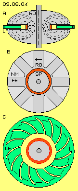 For ´civilian´ applications that start-stop-mode is not usable. Demanded is a periodic change of motion-intensities. This picture at the middle at B shows a cross-sectional view of an according rotor (RO, grey). The coil (SP, red) is winded concentric around the axis. The magnetized iron (FE, dark-grey) however builds only some spokes (here e.g. eight). The sections between the spokes (NM, light-grey) can be empty or filled up by material non-magnetic and non-conductive. The magnetic field no longer is a closed torus. Within the groove now exist a magnetic fields of changing intensity.
Induction comes up by ´pulsating´ magnetic fields and / or relative motion between magnet and conductor. As mentioned upside, the cause of electric flow of the unipolar generators (or the question of perpetuum mobile) is discussed controversial. However one seems to agree in the fact, the stationary current-collector finally represents the demanded relative motion (or the support of suggested contrary force). If this constructional element has decisive importance, it should be build logical stringent.
Already Tesla made the proposal for spiral sections of conductor-disk, in order to optimize the ´electronic flow´. Analogue, here the charge-catcher is divided into some spiral sections. Their curvature (from inside outward) shows into turning sense of system (here assumed left-turning all times). At the rim, the sections of the charge-catcher are connected, for guiding the (somehow pulsating) DC to the consumer.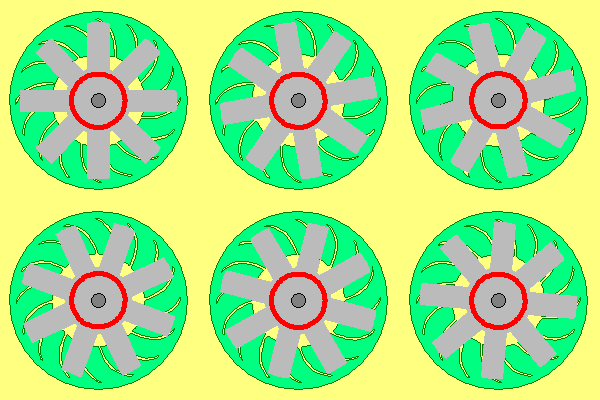 This animation clearly shows the relative motion. The spokes (grey) of the rotor move over the spiral faces of the charge-catcher (green), like ´windscreen wiper´, however by opposite function. Each magnetic field ´smears´ its motion-pattern onto the spiral bands. Thus a layer of intensive aether-movement ´sticks´ at the surface. These are circling movements-with-stroke, deformed to garland-shaped loops. These motions demand a corresponding high aura above the surface. Finally the following gap (respective the non-magnetic fill-material) allows the Free Aether to flatten that ´charge´. The normal aether-pressure thus wipes-off the charge at these spiral tracks (where the garland-shaped stokes already show into wanted direction).
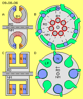 At picture 09.08.06 upside left at A the rotor (RO, grey) is sketched by longitudinal cross-sectional view. That rotor mainly exists by non-magnetic material (NM, light-grey). Embedded are some electro-magnets (EM, dark-grey and red), building a concentrated magnetic field between their north-pole (N, blue) and south-pole (S, red). Upside right the picture shows a corresponding cross-sectional view.
At this picture below at D for example eight charge-catchers (LF, green) are installed at the stator and four magnets at the rotor (RO, light-grey). Here schematic are marked the north-poles (N, blue), moving over the faces of the charge-catches as the rotor is turning around. This arrangement produces DC by two phases or steady pulsating DC.
Unfortunately it´s still an open question, whether N-machines respective unipolar-machines represent a perpetuum mobile or not. As everyone knows it´s not quite simple to measure the energy-input and -output of a system, because each measurement by itself affects the running process. That problem is indisputably solved only if a machine can produce its own drive - and probably produces some energy-surplus. At picture 09.08.07 a proposal for simple construction is sketched.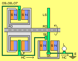 Suitable for drive could be a Faraday-Motor, just because it´s the reversal of that principle and as it demands only simple constructional elements. The stator (below right) is represented by two permanent-magnets, which are connected with a yoke (dark-grey). The rotor is a disk (LS, green) build by electric conductive material (e.g. a copper-disk, fix mounted at the shaft). A sliding contact (SK) feds the current inside and a second contact takes it off at the rim. The conductive disk practically represent many radial wires. When current is running from inside outward and through the magnetic field (see arrow), the Lorentz-force is affecting onto each ´wire´, resulting a turning momentum and thus driving that motor-disk and also the rotor of the generator.
The Free Aether drives the high charge (HC) of the charge-catchers through the whole circuit along the conductor-surfaces, into the sink of normal charge (NC) of the earth. The motor must drive the generator and must overcome the friction within bearings and at the sliding contacts. If finally also a small lamp (L) would shine, the prove for a self-running machine and efficiency beyond 100 percent would be perfect.
09.09. Railgun and Ballbearing-Effects
09. Aether-Elektro-Technics