Crop Circles
At previous chapters concerning the ball-bearing-effect, also appeared some rings and rolling cylinders, which reminded me the crop-circles. However here it´s not the aim to construct complex wheel-systems, but only to produce most intensive aether-swinging movement at conductor-surfaces, thus producing electric current directly. Optimum solutions mostly are based on simple principles and are using ´pretty´ shapes - e.g. like these crop-circles might present diverse impulses.
Simple Rotor, huge Aura
At this picture right upside, the rotor (RO) is drawn by cross-sectional view. The turning disc builds a rigid vortex with increasing speed from the centre outward. The stroke-component of the aether becomes corresponding stronger, with strongest intensity at the rim (see arrows at B). The aether of the environment takes also that stroke in turning sense, however decreasing towards outside, like at any potential-vortex. The balancing movements towards Free Aether occurs within a wide aura, into radial and also into axial direction (again much wider than drawn here).
At this picture right below, once more is repeated how that stroke-component comes up, e.g. by simple overlay of two circled movements. During one half of time, the aether is moving accelerated at a long way (dark-red section C). During the second half of time, it moves back slower at a shorter way (light-red section D). All aether is moving at a local narrow space, thus by that sense it´s ´stationary´. Details are described comprehensive at earlier chapters.
Charge at Rotor-Surface
The charge by itself exists by synchronous swinging aether, here represented by multiple twisted black connecting-lines. Generally, the aether-pressure pushes an electrostatic charge (A, light-green) toward the surface by a layer of likely height - when the rotor does not turn. If however the rotor is turning, the charge-swinging becomes overlaid by the stroke-component of the rotation. The further outside towards the rim of the disc, the more intensive the swinging is, like marked by the thick black connecting-line at B. This strong swinging reaches further out into the space correspondingly (here towards right side).
This picture right side shows a view onto the charge at the surface of the rotor. When the rotor is resting, one can imagine the charge as swinging of neighbouring aether at likely and steady circle tracks, here marked by three circle-arrows at C. At running mode the rotor is rotating (see curved arrow RO). The atoms at the rim are moving most fast within space and analogue the stroke-component there is most strong, here marked by arrows at D. So the circle-movements of the charge are shifted some forward into turning sense of system. Resulting is a ´garland-shaped´ motion-pattern, here schematic sketched at E. Parallel to the turning of the material disc, thus the motion-pattern of the charge is moving forward. By that sense, the electrostatic charge ´sticks´ at the rotating surface.
Charge-Track
At picture 09.11.04 these elements are sketched schematic. The charge-catcher (LF) is fix mounted within the housing, thus is stationary. It exists by non-conductive material (blue), within which are embedded some electric-conductive tracks (yellow). Electrostatic charge can exist also at non-conductors, like e.g. discussed by example of PVC-ruler. The surfaces of these amorphous materials are rough, so the connecting-lines of charge stick on tips or are caught into depressions. The electrostatic charge thus is mostly stationary respective no electric flow can come up at non-conductive materials.
Opposite, the surfaces of conductors are smooth and thus ´slippery´ for charges. As a rule, the atoms of conductors are arranged by grids, so the charge e.g. can swing garland-shaped from one atom to the next. The charge-tracks of the charge-catcher now must show shapes to achieve a flow of charge into wanted directions.
Inward-Drift
Left side at A the conductor-tracks are in shape of previous three rings, including each other. A part of the charge momentary is positioned e.g. at location D. It wanders inward to position E, driven by the thrust of the rotor-charge. The strong and fast strokes at the rim of the system (respective the intensive charge) thus is guided inward to a shorter radius - and there is turning faster than the rotor. Analogue the charges are shifted inward at the other track-rings.
At the middle of this picture at B, the general pattern of ´half-moon crop-circles´ is drawn. There are three conductive tracks (yellow, red, green), each with a wide and a narrow section. The charge of the wide section is pushed to the bottleneck, here e.g. from area F to G (and analogue at both other tracks). The charges are guided inward to a shorter radius - with their ´oversize´ speeds - and in addition are piled up at each narrow-pass.
Steady Current
The aether-movements accumulate at each shortest radius, what´s equal to high charge respective strong voltage - e.g. versus the normal-voltage of the ground. At previous picture 09.11.04 thus schematic is sketched, the high charge can flow off along a conductor (red) into the ground (E) and that permanent current is usable by a consumer (V, blue). Depending on the shape of construction, the current is removable at different spots, e.g. at the three simple rings from each inside part, at the three half-moons from each bottleneck, at that flower-pattern from the ring inside.
Source and Sink
Already the fast and steady rotation of a massive disc produces a wide aura of synchronous ´turning´ aether (in reality only that motion-patter with stroke-component all around into radial and axial directions). The unipolar-machines of previous chapters used magnets and their field-lines contributed an additional swinging motion-pattern. Here now when starting the system, the rotor-faces are covered with a charge-layer. Their ordered motion-pattern is added to the aether-aura of the rotating rotor. That intensive swinging is guided inward by the charge-tracks and is concentrated at the centre of the system. There is piled-up high charge-density, rotating around the system-axis by ´oversize´ speed (which could even result a self-accelerating effect).
Versus the environment thus exists a gradient of motion-intensity. This results from the motion-pattern of original rotor-charge, which is ´turned-up´ by the rotation of the rotor, and is guided inward along the stator-tracks. That motion-pattern of general electric charges represents high voltage. If a way towards areas of less motion-intensity is opened for that potential, a current runs along that conductor towards the ground, also through a consumer. This small unit produces strong swirls within the aether between the rotor and the stator. This local accumulation of ´stressing´ movements is pushed off by the general pressure of surrounding aether into the sink of normal charge-density - and as a side-effect the electric current is usable for a consumer.
Pulsating Current-Circuit
The edges of spiral-arms often are pointed out at the sun-wheel crop-circles. Here these edges are interpreted to exist at different axial levels, thus at the one hand as parts of the stator and at the other hand as parts of the rotor. The frontside-edges (E, yellow) thus are assumed to be charge-tracks of the stator, which are combined to a ring in the middle. The stronger curved backward-edges (F, green) represent areas of the rotor-charge. At this picture right side at B, the rotor did turn little bit (see thin arrow). The green rotor-edge F did pass the yellow stator-track. The crossing-point of both curves did move inward very fast (see thick arrow).
Below left side at C schematic is sketched a cross-section. The stator (ST) exists of non-conductive material (blue) and only some (spiral curved) charge-tracks (LF, yellow) reach some out of the face. Charge sticks at that radial spoke, here marked as light-green area. The rotor (RO) might exist by iron (grey), however its surface mostly is covered by a non-conductive layer (pink). Only some (spiral curved) spokes reach some out of the surface. At the (rounded) face of these spokes the strong rotor-charge is concentrated, here marked as dark-green area. As long as the rotor does not turn, no interaction between both charges exists.
Below right side at D the rotor is moving (see arrow) and thus the rotor-spokes are crossing below the yellow stator-spokes. The strong charge (G, dark-green) of the rotor pushes ahead the weaker charge of the stator. A charge-hill is piled up (see arrow H) and is shifted inward along the curved charge-track of the stator. This interaction between ´electric fields´ is commonly known. The reason and the basic movements of the real aether-background are discussed at chapter 09.04. ´Charge´ at picture 09.04.04.
At the same moment the charge-hills of all charge-tracks arrive at the central ring and add-up to high potential. If at this moment a conductive way is opened, the voltage can relax by current-impulse flowing off. In reality, the high and intensive swinging charge-layer is compressed and levelled along the conductor down to the sink.
Function-Model
For starting the system, the rotor must be charged from an external source (A), e.g. by gliding-contact at the shaft. For stopping the system, the charge must be allowed to flow-off to the ground (B). This system might become self-accelerating. So that switch for discharge must be installed at any case.
The charge of the rotor looses strength only by radiations. The control-unit could produce stronger voltage by a transformer and if necessary could balance the losses via conductor E (and the directions of all flows naturally must be controlled by diodes etc.). This function could also be used for first supply when starting the system or in running mode for increasing the voltages. Correspondingly also the original charge of the charge-tracks could be increased via transformer and conductor F (up to previous relation of charge-strength). So by suitable controlling this generator could produce current-flows of variable strength.
Constructional Variations
If for example ten spiral spokes are installed, hundred current-impulses are available by only 600 rpm. This machine could show a diameter of e.g. 40 cm and thus wide faces for rotor-charge and stator-tracks are available. So this generator could produce a performance of usable size. Next chapter will show an other variation inclusive control by mechanic elements.
Crop-circle-pictograms come up frequently since some years, especially in England and also in other countries. Naturally there are fakes, however some are designed by high quality only ´intelligent beings´ were able to produce. I do not want to convince anybody, however I assume the ´authentic´ crop circles are ´anybody´s´ essential messages. Unfortunately we mostly are too stupid to understand the coded information.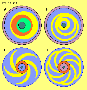 Around the turn of century, often came up motifs like shown at picture 09.11.01, where the elements are differed by some colours. At this time I studies rotor-systems in order to produce a turning momentum based on centrifugal- and/or gravity-forces (e.g. by embedded wheels and eccentric rings). Unfortunately no pure mechanical ´perpetuum mobile´ was successful up to now (even Johann Bessler alias Offyreus might have build a running wheel some hundred years ago).
At picture 09.11.02 a simple disc is fix mounted at a shaft (dark-grey) and this rotor (RO, light-grey) is turning around the system axis. However in reality, no ´solid particles´ are moving within space. The atoms are only complex vortices of aether and only their motion-pattern are forwarded within the aether, which by itself is generally stationary. Strange appearances occur even by such simple constructions. If e.g. the disc is build by iron (FE) and is rotating fast and long time, the ´spin´ of the atoms becomes adjusted and the material becomes ´magnetic´. The real cause is the following: the vortices of atoms are not completely symmetric, the ´bulky´ parts stay back within the aether, so the whole vortex-assembly is aligned that kind, the resistance becomes minimum. If many atoms now are adjusted alike, also the aether between the atoms shows an ordered motion-pattern. If these aether-movements behave analogue to magnetic field-lines, the rotor-disc appears like a (week) magnet.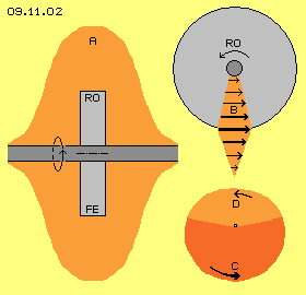 If the vortex-complex of an atom has passed an area of the stationary aether, afterward this region comes back to its original motion-pattern of Free Aether. If however many atoms repeatedly are crossing the area, the aether of that region does not come back completely to the neutral motion-pattern. The atoms practically leave a trace. The swinging becomes deformed, as it´s moving fast into direction of turning sense and coming back some slower. As all ather is a gapless whole, neighbouring aether must take also that stroke-component. Around the rotating disc thus appears a wide-ranged aura (A, light-red). This area of likely aether-movements is much wider than sketched here, especially if magnets are rotating. The aura e.g. around John Searl´s disc was even visible. At the experiments of Roschtschin (other spellings are Roschin or Rochtchin) and Godin, the effects were detected even at rooms aside and upside floors (see previous chapter). Diverse inventors used that side-effect of ´fly-wheels´, mostly without knowing that aether-background.
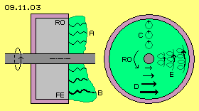 Like the machines of previous chapters, the system must be charged for starting. So the second constructional element is the electrostatic charge at the surface of the rotor. Charge must exist only at one side-face of the disc. At picture 09.11.03 thus the rotor (RO, light-grey) is covered by an isolating material (pink) at the other faces. The rotor is build wider than necessary for the charge, so the aether-movements can build up most strong within the rotor-masses and the enclosing aura.
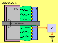 A most simple system is achieved if this simple rotor is the unique moving part. The charge of the rotor is parallel rotating to the disc. The stroke-component is added to the normal swinging of charge. Already at a disc with a diameter of few centimetre, the motion at the rim is much more intensive that at the centre. Now the aim is to spread that strong charge-swinging into whole inner room respective to guide it into wanted direction. This is the function of the third constructional element, which - analogue to earlier chapters - is called ´charge-catcher´.
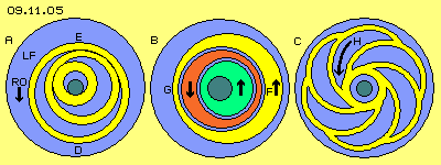 Corresponding to previous sketched crop-circles, picture 09.11.05 shows three alternative arrangements of tracks at the charge-catcher (LF). The stator mainly exists by non-conductive material (blue). Embedded are conductive tracks (yellow). The rotor is left-turning and also its charge is moving left-turning over the faces of the stationary conductor-tracks (see arrow RO).
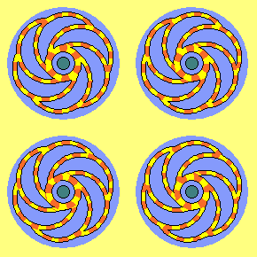 Right side at this picture at C, the frequent graph of the ´flower-pattern´ is drawn. The borders of the ´flower-petal´ represent the conductive tracks (yellow). The left-turning stator-charge continuously is shifting inward the stator-charges, like marked by arrow H. The charge-tracks build a ring at the centre, where finally all charges are piled up. At this animation, separated sections of the charges are marked red. All charges wander inward and meet at the central ring, building a high layer of fast turning charge.
Once more I´ll underline these facts: here does not flow a current existing by ´charge-particles´ like electrons. Here does not occur a shift of ´charge-masses´. Only the motion-pattern of electric charges are forwarded within the basically stationary aether. Within that gapless medium, neighbouring aether must move analogue at its best. Here for example the motion-pattern of rotor-atoms are moving around the system axis. Correspondingly the motion-pattern of the rotor-charge rotates around. Also the aether at the faces of the stationary charge-tracks take-over these charge-swinging motions. Unhindered and undiminished the rotor-charge-layer still turns around the system-axis. The generated movements at the charge-tracks can follow the stroke-component not completely (into the original tangential directions), however the charge-layer can slide inward along the tracks. Each inside neighbouring aether-areas take-over the stroke-component. As the rotor permanently crosses below the charge-catcher, finally all aether along the charge-tracks becomes swinging by that inward directed component.
A permanent electric flow ´from the nothing´ naturally is a provocative idea. However, also for the Faraday-Generator (and the other unipolar-generators of previous chapters) the source and cause of generated currents are inexplicable by common physical understanding of electricity. Also at a PVC-ruler and a wool-sheet no charge exists originally. Finally by the rubbing action the electrostatic charge comes up and can be taken-off e.g. by a copper-brush - and new rubbing produces new charge. Previous rotor could show a diameter of 10 or 15 cm and could drive 10000 or even 20000 rpm, so would ´rub´ along the stator by high speed. Instead of the wool-sheet, here the rotor-charge swirls up the aether at the stator-faces (also at their ´PVC-regions´). Instead of previous copper-brush here the charge-tracks build a conductive way along which the charge-vortices can flow-off.
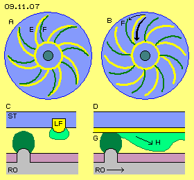 Instead of continuous current, naturally the voltage could be dammed up and flow-off intermittently. A variation for generating pulsating current is discussed at the following. The functions of this generator can be explained also by common understanding of electricity. This conception is based on the frequent crop-circle motif of ´sun-wheels´, e.g. like drawn at previous picture 09.11.01 at C. Here at picture 09.11.07 left side at A is drawn a sun-wheel, for example with eight spiral arms.
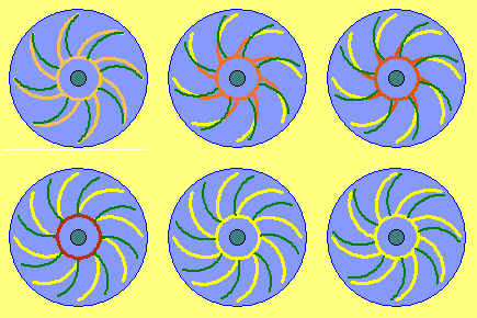 At this animation the rotor-charge-spokes (green) are crossing over the stationary charge-tracks. The original charge (yellow) is pressed inward at each crossing-point of both curves. The ´compression´ of charges here is marked by increasing dark-red colour. When the crossing-points arrived at the central ring, the charge-tracks are ´swept clean´. All charge is piled up at the inner ring. If a switch opens a conductor-way, the current flows off to a consumer. From there, next moment, it can flow back into the ´empty´ charge-tracks. The remaining current-strength builds the new charge-layer of the stator. That low charge is compressed again at next phase. So a pulsating circuit of current is running around within a closed conductive loop.
The conception in principle and previous processes are sketched schematic at picture 09.11.09. Within an isolated housing (GE, pink) the rotor (RO, grey) is turning. At one side-face (here right side) the curved spokes reach some out of the surface and hold the strong rotor-charge (dark-green). Opposite of, the stator (ST, dark-blue) is installed, where curved spokes of charge-tracks (LF, yellow) reach some out of the surface. All charge-tracks meet at the middle at the inner-ring (IR, yellow). The alternative ways for electric flows are marked by red lines. There are also marked a consumer (V, light-blue) and a control-unit (S, light-blue). Its technical elements are not drawn in details, but its principle functions are verbal described at the following.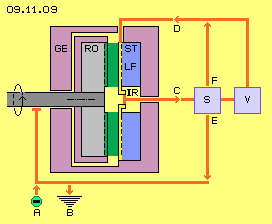 At running mode, the charge along the charge-tracks is compressed into the inner-ring (IR, yellow). When maximum voltage is achieved, the control-unit must open the way C. The current is used by the consumer and flows back to the outside ends of the stator-spokes via conductor D. There the remaining charge spreads on the faces of the charge-tracks and the face of the inner-ring. The compression of charge occurs in relation of these surfaces. The original charge thus could rise e.g. to triple charge-density at the inner-ring. The rotor-charge must be at least comparable strong (rotating charges are intensive aether-vortices, thus always stronger than comparable charge at resting surfaces).
Naturally this principle can be realized by multiple variations. A mechanical drive is necessary at any case for running the system. Common generators use magnets with corresponding back-effecting forces. Here only electric fields respective charges are interacting, so the motor must overcome only the friction of bearings. Current-impulses are generated corresponding to the speed of revolutions.
09.12. Tilley-Cone-Generator
09. Aether-Electro-Technics