Objective
Below at this picture at B, the general principle of that new ´booster-conception´ is sketched. From a charge-source of low voltage (C24, white), the current is guided into the ´volt-booster´ (VB, green), where the voltage rises up and the current respective charge is shifted into a high-voltage-storage (C48, white). The following current for balancing the voltage-difference is usable for consumers (V, blue).
Compress on smaller Face
That compression could also be done continuously, e.g. if the storage is shaped like a band with decreasing width. That storage-band CB (with differing green) is sketched at this picture at B. The reduction in size is given e.g. when the storage-band is arranged at a cone - and this remembers at previous mentioned ´Tilley-Cone-Generator´ (if my interpretation of his vague hints is correct).
Upside right at C, the jacket-face of the cone-trunk of the stator (ST) is drawn. On the non-conductive material (NL, grey), here e.g. four storage-bands (CB, light green) are arranged. At the wide end of the cone, they are rather wide and they become smaller to the narrow end of the cone. The bands are arranged diagonal. From the wide to the narrow end of the cone, they show forward into turning sense of system (here assumed all times left-turning).
Below right at D, the jacket-face of the rotor (RO) is drawn (here by likely size, really however it´s little bit smaller). Dielectricum-bands (DI, violet) are installed at the non-conductive material (NL, grey), some above the surface. Here are drawn four bands. Their contours are similar to the storage-bands. They are also arranged diagonal, however the dielectricum-bands are in front (in turning sense) at the wide end of the cone. Both bands thus are positioned right-angles to each other. As the rotor is turning, the charge at the storage-bands is shifted to their narrow ends (see arrow upside at F). As the rotor-cone-trunk is build by non-conductive material, these dielectricum-bands could exist by same material, i.e. build by ribs (or bars) some above the cone-surface.
Tilley well could have achieved stronger performance from the batteries by that conception, when charge is compressed onto each smaller face and thus the voltage is pushed up. He mentioned, one could buy the material for that ´spinner´ at any store for little money - fitting to that simple construction. He mentioned, most problems would make the isolation of the housing. Obviously he had losses by radiation of charge. One reason could be, the backward faces of the storage-bands are embedded within non-conductive housing, nevertheless the charge there could move-off during the compression.
Storage-Disc
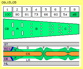
That picture left side shows a cross-sectional view through the housing (GE, grey). Previous storage-band here stands cross to the longitudinal axis in shape of a disc (CS, light green). This storage-face is installed ring-shaped along the inner side of the housing. The storage-face has one connection towards outside for the inlet and one for the outlet (IN and OUT). Near to the inlet, the face reaches far inside, so there the surface is relative wide. In turning sense, the surface becomes smaller and decreases to the half near to the outlet. That disc can be fixed direct at the housing. However the turning rotor swirls air around the inner room. So the storage-disc preferably should be embedded within a disc of non-conductive material (NL, light grey), building a plane surface over all.
At the middle of the picture, a longitudinal cross-sectional view through the system axis is drawn (one situation at half upside, an other situation at the half below). Upside, both sides of the storage-disc momentary are covered by the dielectricum (DI, violet). When the rotor (RO) is turning, aside the storage-disc exists free space. Into that space reaches the swinging motion of the charge (LA). That situation is sketched below at that schematic longitudinal view.
Seven Modules, eight Sections
Upside the rotor was drawn as a four-arm star. So all times, four sections are covered by the dielectricum and at four sections the charge can reach into the room aside of the storage-disc. The sections (numbers 1 to 8 at first row of picture 09.15.05) must show each smaller surface. If the width of each section decreases by 1/10 (e.g. from 100 to 90 and 81 etc., finally to 48, see second row of the picture), at the very end the width of the band respective the face will be half. When the dielectricum glides (here from left to right) over that storage-band (CB, light green) of decreasing size, the charge becomes compressed and at the outlet will exist double voltage.
In order to avoid ´fading´ (backward wandering charge) the storage-band (CB, light green) should be divided into sections, e.g. by bottle-necks build by slots (like sketched at A). That constructional characteristic is adopted from the Testatika, where such slots are arranged within the storage-faces (and the inventor Baumann underlined, that would be most important). The sections could also be build by a row of holes (like sketched at B), also by several rows and some shifted (like sketched at C). These holes could be 1 to 2 mm wide, with rounded edges and separated one from the next by about 3 to 5 mm distance (however the optimum must be found by experiments). The importance of that ´perforation´ is explained by lower part of that picture.
Perforation
Left side at this picture is drawn a part of the rotor (respective the dielectricum, RO and DI, violet), moving to right side (see arrow). It´s frontside should be ´plough-shaped´ and build by metal (blue), like discussed at previous chapter: this constructional element rotates within an area filled up by charge and it´s gliding along charged storage-faces all times. Soon it will become charged by itself, the metallic frontside and whole dielectric part as well (e.g. like a PCV-ruler). This constructional element (by its materia and in addition by its own charge) affects pressure onto the storage-surface (see diagonal arrows). The charge at the storage-surface is piled up (at E) and transported forward.
At F is a hole within the storage-sheet. However, there won´t be a gap within the charge. Opposite, contrary swinging charge-motions meet at the inner sides of the hole, so aether-´stress´ comes up at the border-line between (dark-green lines). The hole practically builds a Faraday-cup, so at its border the charge is compressed and accumulated (dark green areas). Already a depression within the storage-surface (at G) causes the building-up of a ´hill´ within the charge-layer.
Stronger Thrust
If now the dielectricum arrives at a hole or depression, the previous piled-up charge (marked by arrow at F) is pushed into that deepening. A reflection occurs and that whirl-up again increases the charge-hill. Thus the dielectricum can sweep-away a most greater part of the charge. At the other hand, that impulsive crash of aether-motions into the gaps of holes or depressions affects a ´shock´ on the atoms of the conductor. At its outer regions thus comes up a ´material´ motion - i.e. not only the charge-displacement but also current are achieved (like discussed at following chapters).
That ´perforation´ of the conductive surface enforces extremely the effect of charge-shifting and thus of generating electric current. So this technology should also be used at the ´Electric-Ring-Generator´ of previous chapter. The possible result is shown at following picture 09.15.06.
Charge Accumulation
Analogue, from each following section 1/10 of its charge is shifted forward and there that part of charge is compressed by 1/10. After short time the sections from left to right will show increasing charge-units. At this soft inclination, no ´fading´ respective back-flow occurs: if e.g. 3.0 units of section 3 are pushed forward by the dielectricum, it leaves behind an ´empty´ section 3 of 29.6 - 3.0 = 26.6 units. This corresponds exact to the charge-splash which is pushed forward by the next dielectricum from section 2 into section 3. So the charge-transports from one section to the next are done by minimum resistance.
Multistage Compression
Modules 1 and 2 are fed with charge corresponding to 24 V (marked light green). Based on previous procedure, at the eighth section respective at the outlets the voltage rises up to 48 V. Both charge-volumes are guided into the inlet of section 3. Its first section can take that charge without problems, because its surface has double size (of section 8 at first level). At that second stage, the charge is transferred from 48 V to 96 V at the outlet. Analogue process occurs right side at the modules 7, 6 and 5 (see red arrows). At third stage, the charges from modules 3 and 5 once more are combined into the inlet of module 4. At its outlet finally all charges are available with the voltage of 192 V (see green arrow).
Only real experiments can show which voltage of charges are achieved in reality. If that shifting takes these 10 percent, that three-stage ´pump´ results eight-fold performance (24-48-96-192). If only five percent could be involved, about three-fold voltage would be achieved (24-36-54-81). If however 15 percent of the charges could be seized, factor 3 would result with much higher values (24-72-216-648).
Performance Surplus
As an example, the dielectricum pushes forward 1/10 of the 24 charge-units of section 1, thus moving off 2.4 units. Section 1 remains ´empty´ resp. now has only the charge corresponding to 21.6 units. So these 2.4 units must be reloaded, four times into previous modules 1 and 2, also into modules 6 and 7, at same time, by 24 V voltage. The amperage fed into the input is transported through the whole system and the same amount of amperage leaves the system via the outlet of module 4, at same time sequence, however by 192 V output-voltage. So the decisive performance-surplus in comparison with a normal transformer comes up, because the same amperage is available, however with stronger voltage. The decisive difference in comparison with a normal generator comes up, that volt-booster needs much less power for the mechanical drive.
Charge must be shifted within this system, however moving forward the dielectricum along a conductive surface is nearby force-neutral (as explained at previous chapter ´Capacitor-Mystery´). When current is flowing through that storage-disc, also electro-magnetic forces come up (all times forward-left-turning). Here however, no contrary forces exist. There is only charge respective current running, well protected by the non-conductive isolating housing, all times forward into same direction. The essential part of the performance is done by the Free Aether, as it pushes the compressed charge to the consumer by increased force. Tilley stated, one third of the energy is necessary for keeping the system running, so two third of the energy are available for driving a car or electric tools or lightning. That third is also mentioned at other comparable systems, e.g. also at heat-pumps which draw additional energy from the environment.
General Design
However this simple conception won´t work. The electrons won´t leave the plus-pole ´voluntary´, e.g. for starting the procedure. The current from a battery must flow within a closed loop all times, normally from minus- to plus-pole. However also when charging batteries, the internal chemical processes need a constant relation between surplus and lack of electrons. That´s why that system needs additional elements, especially for starting the system, e.g. some capacitors or intermediate storages.
With these intermediate storages one is no longer bound to the obligatory closed circuit when using batteries. Changing demands for current are better to manage when using wide intermediate storages. Recharging the storage of high voltage (CH) must not run totally synchronous to demanded current, but can be done some time-shifted. Depending on demand, the volt-booster can work with varying speed and / or different input-voltage. Opposite, one can stock-up the storage of high voltage in advance. The wider the intermediate storages are, the more stabile and flexible the system can be controlled.
Large Intermediate-Storage
The storage-faces are build by bare round copper- or aluminium-pipes with radius of 4, 5, 6 and 7 cm (see green rings). There is enough ´air-space´ for the charge at both sides of each pipe. The Free Aether needs that room for working effective. In order to differ the charges, between the hollow copper cylinders should be installed thin isolating pipes (here not drawn). By the length of about 25 cm, a surface of about 0.7 m^2 is available for the storage of low voltage (CN, green).
Within same housing could be installed the storage for high voltage (CH, red) by pipes with diameter of 9, 10, 11 and 12 cm. Both sides of these pipes build a surface of about 1.3 m^2. At both storage-areas (CN and CH) here are drawn an inlet and an outlet (IN and OUT). All pipes of an area are conductive connected. So this storage has an area of low and an area of high voltage, however this might not be mixed up with a common capacitor. Also the Testatika used big ´Leidener-Bottles´ with internal connected faces. That´s rather difficult to understand for experts, because it makes no sense based on the idea of positive / negative charges. However these pipes are advantageous round storage-faces - for exclusive existing negative charges. How much Coulomb by which voltage one finally can store at these free storage faces - no expert dared to tell me (because here the common capacitor-formula are not valid).
Running Mode
Opposite, between the storage of low voltage and the inlet of the volt-booster (between CN24 an VB) exists only a small gradient. The average level of section 1 is about 24.0 V (against the earth). One tenth is transferred into section 2. The dielectricum leaves behind an ´empty´ section 1 with 24.0 - 2.4 = 21.6 V. So the difference to the storage of low voltage are only these 2.4 V. Probably no sufficient balancing-flow will come up, because the charge should run ´by itself´ from CN24 into section 1 of the volt-booster within relative short time.
This charge-process could be ensured by an transformer (T1, blue, below left). It should press the secondary-current from storage CN24 with few increased voltage into section 1, at the very moment when the inlet is opened. This transformer T1 is supplied by an accumulator (A1, blue, below left), which also supplies the mechanical drive (MO, blue) of the volt-booster.
Performance-Input and -Output
So keeping up the running mode demands about one third of the cross-performance (see Tilley). Remaining are about 500 W for external usage. These could be used for charging further accumulators (T3 and A3), which might drive other external consumers. The remaining performance could also be adapted for demands of other consumers (T4 and V). The performance of that volt-booster depends on the charge-volume fed into the storage-faces. Probably the input-voltage of these 24 V is too weak. The performance surplus could be ten times higher, if e.g. 220 V would be used as basic input (by practically unchanged efforts for the construction and energy for mechanical drive). Following additional points of view might also result quite different performance.
Alternative Storage-Discs
Alternative Rotor
If the assumed charge-compression can not be achieved, two stages, previous three stages or even four stages must be used to achieve the wanted outlet-voltage. If however at first stage already a sufficient increasing voltage can be achieved, many modules could be installed one beside the next and thus the charge-throughput would increase. At previous picture below, for example 18 modules are sketched at the shaft and this booster-cylinder might be about 60 cm long. The modules could be shifted by 20 degree, thus at the outlet would exist nearby continuous DC. At the other hand, thus also the flow into the inlets would be a rather steady stream.
Alternative Feeding
Alternative Trafo
Analogue to the ´Hydrostatic Ram´, that abrupt stop of the (water- respective current-) flow results an enormous rise-up of pressure, here in shape of the expansion of the electromagnetic field around the coil. Up to that moment, also the conductive connections of the secondary coil (to and from the consumer V) should be interrupted, at the one hand by a diode and at the other hand by a switch (DV and SV, blue). Finally when that switch opens the way to the consumer, the blown-up field ´implodes´. The ambient aether compresses that motion-cloud. Because momentary the only exit exists towards the consumer, the whole jammed-up motion-potential runs off as an extreme strong current-impulse.
Alternative Storages
Today, cars with electric drive show a range of about 200 km and their accumulators deliver hundreds of ampere. Only a small part of would be necessary, complemented by additional charge-storages of previous discussed shape. In combination with that volt-booster likely performance would be achieved with unlimited range - and no recharging at power-points would be necessary. Also the wall-sockets at home naturally could deliver unlimited current by a corresponding unit. I hope these perspectives will encourage many experts to check these proposals seriously.
Recently rumours came up about ´power-boosters´ where the voltage was increased - by constant amperage. Such a machine could take more performance e.g. from a car-battery. Already Tilley did drive electric vehicles, where the batteries still showed the original voltage at the end of the trip (probably, see chapter 09.12. ´Tilley-Cone-Generator´). Objective of this chapter thus is the conception for a ´volt-booster´ and an autonomous running system. The base for the following considerations is previous chapter of the ´Electro-Ring-Generator´. Additional points of view are included from the ´Testatika´ (which completely will be discussed at a separate chapter some later).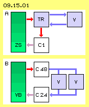 The general principle of previous ´Ring-Generator´ is sketched at picture 09.15.01 at A upside. A charge-storage (C1, white) and an intermediate storage (ZS, green) are charged at same level. At a first phase, a part of the charge from C1 is pushed into the intermediate storage ZS. At the following phase occurs the balancing of voltage by a current-impulse running through a transformer (TR, blue). The generated secondary current is usable by a consumer (V, blue). That procedure is repeated.
Previous chapters explained why charge can be shifted from one storage to an other by usage of a dielectricum. If now each next storage has a smaller surface, the charge becomes compressed, i.e. stronger voltage results. At picture 09.15.02 upside left at A that´s roughly sketched by storages C1, C2 and C3.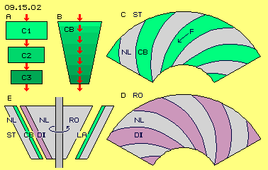 At this picture below left at E, such a cone-trunk is sketched. The housing as stator (ST, grey) is build by non-conductive material (NL). At the inner side of that hollow cone, several storage-bands (CB, green) are installed. Also the rotor (RO, grey) is build by non-conductive material. At its surface, at least two bands of dielectric material (DI, violet) are arranged. Between these bands, an empty room exists, like schematic here shown at right part of the longitudinal cross-sectional view. The swinging motions of the charge (LA) reach into that room - if momentary they are not pushed forward by the dielectricum.
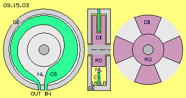 The arrangement, sketched at picture 09.15.03, avoids such problems and works much more effective. Previous storage-bands here are arranged disc-shaped and radial (at right angles) to the system axis. Charge sticks at both sides of the disc. The dielectricum glides aside the disc-faces with narrow distance, so charge is shifted forward in turning sense of the system.
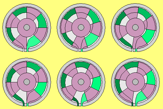 This picture right side shows the rotor. Here for example, it´s drawn with four arms of dielectricum (DI, violet). These arms enclose the storage-disc at both sides and glide along by most possible small distance. Charge is shifted forward on each smaller faces and thus the charge-density and voltage increases. The animation shows that compression, marked by different green colours.
One module of that volt-booster will show a diameter of 25 to 30 cm, however only about 3 cm width. The storage-disc is build by copper- or aluminium-sheet, which will be stable enough by about 2 mm thickness. As only small voltages exist (e.g. starting with 24 V) the distance aside of 6 mm will give space enough for the charge-clouds. Within that room, the dielectricum might be about 4 mm thick. The isolating walls of the housing must also be only some millimeter thick. Thus within a round cylinder of about 25 cm length e.g. seven modules could be installed, one besides the next at the system shaft.
 There is drawn a cross-section through the storage-disc (CS, here marked red). At its side-surfaces exists charge (LA, light green). If these surfaces momentary are not covered by the dielectricum (at D), the swinging motions of the charge reach out into the space aside. The housing respective the stator (ST, grey) of non-conductive material (NL) builds the borders for that room. Normally, the general pressure of Free Aether presses down all charges to likely level at a surface (here marked by dark-green lines, see e.g. at D).
The displacement of charge by a dielectricum is depending essentially on the distance of the gap to the conductive surface. That rotor here is a rather simple construction, at previous example with length and diameter of only about 25 cm. Nevertheless that rotating part will show swinging motions, so the gap between dielectricum and storage-disc could be 0.5 mm at its best. However, just near to the surface exists the main and most intensive part of charge-swinging movements.
At row A again the sections of the storage-disc are listed by 1 to 8. All sections (at row D) at first are charged by a strength corresponding to 24 V (against the earth). It´s assumed, only 1/10 of charge is transported forward, when the dielectricum glides over the storage-disc (so here from left to right). From these 24 charge-units of section 1 thus 2.4 units are moved to section 2 (see row B, violet). There exists 1/10 less surface for that volume, so the charge of section 2 again is increased by 0.2 units (row C, light green). The charge of section 2 thus now shows 24.0 + 2.4 + 0.2 = 26.6 units.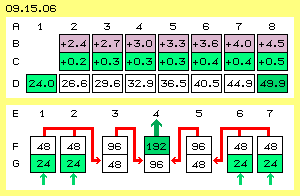 Finally at section 8 a charge-volume is accumulated corresponding to 49.9 Volt (against the earth). As here is assumed, only the small part of one tenth of each charge is pushed forward and that part is compressed into a face only 1/10 smaller, after eight steps the double voltage is achieved. If really only the half (1/20) could be achieved, the factor would by 1.5, thus increasing 24 V up to 36 V. If however 15 % of the charge could be involved, factor 3 would result, transferring 24 V up to 72 V.
Upside was mentioned, the volt-booster could be build by seven modules one aside the next at one shaft. These modules are numbered 1 to 7 at row E. Row G represents the inlet of the modules and row F represents their outlet. All modules are constructed likely.
One can produce an amperage of 24 V with a normal generator, or 48 V or 96 V. However one needs double or four-fold input, because the mechanic energy is transferred only 1:1 into electric energy. One can transform the voltage of 24 V to 48 V or 96 V with a normal transformer, however the amperage will decrease correspondingly. The electric performance P=U*I keeps constant. That volt-booster however produces an increased voltage by unchanged amperage. If previous multistage ´pump´ compresses the input-voltage of 24 V up to output-voltage of 192 V, results an eight-fold performance.
At picture 09.15.07 upside is sketched how Tilley might have used his ´spinner´ (SP, green) for charging batteries (BA, blue). The spinner draws ´electrons´ from the plus-pole, transforms them to stronger voltage and pushes them back into the minus-pole. Here are drawn three batteries: one for the motor (MO, blue) for driving the spinner (and control-units for internal processes), two for external usage (e.g. for driving vehicles or tools or for lightning etc.). Probably he also used batteries parallel for stronger voltage. Depending on energy-demand, the batteries are reloaded, even alternating.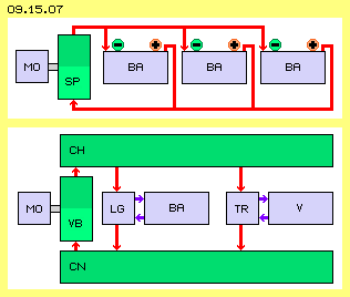 These problems are avoided if generally the input and the output of the volt-booster comes from / runs into an intermediate storage. This principle design is shown below at this picture. Into the volt-booster (VB, green) flows charge from an intermediate storage (CN) of low voltage and pressed the charge into an intermediate storage (CH) of high voltage. The voltage-difference between both storages can be used as a current-flow via conductive connections. A battery (BA, blue) can be charged by a battery-charger unit (LG, blue). At least one accumulator must be available for the motor (MO, blue) and internal control-units. A transformer (TR, blue) can build demanded shape of current for consumers (V, blue).
 Picture 09.15.08 upside right shows the round cylinder of a volt-booster (VB) with seven modules. At previous example, its length and diameter would be some 25 cm to 30 cm. An intermediate storage (ZS, upside left) could also be a round cylinder of comparable size. A longitudinal cross-sectional view schematic is drawn below left side and its cross-section below right side.
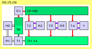 At picture 09.15.09 previous principle design is added by some functional elements. Generally, for starting the system all storages and accumulators must be charged. At running mode, the volt-booster (VB, green) pushes charge into the storage of high voltage (CH192, dark green). A diode (D1, blue) must avoid back-flowing (from CH192 to VB), e.g. if the volt-booster is not working momentary. Based on the high potential-gradient to the storage of low voltage (from CH192 to CN24), current will flow as soon as a conductive connection is available.
The volt-booster of previous example takes charge into four modules (1 and 2 plus 6 and 7) e.g. of one ampere with a voltage of about 24 V, every second. The performance is P=U*I, so here the input is (4*1)*24 = 96 W. The volt-booster at the outlet of module 4 delivers these 4 ampere also each second, now however with the voltage of 192 V, so here the output is 4*192 = 768 W. For continuous running mode, the performance taken from the storage of low voltage must be reloaded. No matter which way, thus 4 ampere with 24 V, corresponding to 96 W, must be fed into the storage of low voltage. Also the consumption from accumulator A1 must be replaced same time, e.g. by recharging a second accumulator by an other transformer (T2 and A2, blue, at the middle of the picture, where A2 could also be identical with A1.
Generally the processes before and behind the volt-booster are done with known technologies. New however is the technique of the volt-booster by itself. The optimum for its diverse elements might be found only by experiments. At previous storage-disc for example, the decreasing size of the surface was assumed by halves. However it must be checked, which compression will show the best results. An essential element e.g. is the ´perforation´ of the storage faces. It must be checked, which kind of deepening are the optimum. Instead of dividing into eight sections, the deep spots could be spread continuously at the storage disc. It´s also necessary to check how wide the free room for the charge aside of the disc should be.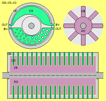 At picture 09.15.10 upside left are drawn alternative arrangements of the storage-disc (CS, light green). The assembly of the machine would be most easier, if the stator is build by two half-shells. This would demand also two storage-discs, each only one half-circle long. At the rim, thus also two inlet and outlet connections (IN and OUT) are necessary. At the upside half of the cross-sectional view, the size of the face decreases continuously from the inlet to the outlet. As an alternative, at the half below the storage disc is drawn with constant width. The reduction of available face could be achieved by the number, the size and the distance of the holes.
That concerns also the optimum design of the rotor, e.g. which material should be used as dielectricum, especially the material and shape of its front face. Upside, the rotor was drawn as a four-arm star. Probably only two arms might be sufficient. Opposite, the dielectric faces could be smaller and six or more arms could be installed. At picture 09.15.10 upside right a rotor (RO, violet) is drawn with eight dielectricum-arms (DI) and thus the frequency of charge-throughput increases. If the rotor is running e.g. with 1500 rpm, previous four arms deliver 100 impulses each second. If one uses double storage-bands, double arms and double revolutions, the performance increases eight-fold (in comparison with upside example).
As mentioned upside, the feeding of charge into the inlet of the volt-booster is a critical point. At the upside picture, the transformer T1 was used. As an alternative, the feeding could occur direct from the storage of high voltage CH192 via controllable resistor. This would also allow to drive variable inlet-voltages. As an other alternative could be used a generator, even mounted direct at the shaft, for pushing charge from the storage of low voltage CN24 into the booster-inlet at the right phases. If necessary, this generator could be used for starting-up the system from the beginning, where the source of charge could be the body of a vehicle or even the basic potential of the earth.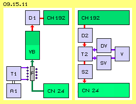 At the picture 09.15.11 left side is sketched an other possibility. Below left are drawn the server-accumulator A1 and the transformer T1. The connection from the storage of low voltage towards the booster (from CN24 to VB) is partly build by iron-material (F, grey) with a coil around. The transformer (or a ´trigger´) delivers only short and weak impulses into that coil, however all times into same direction. Thus the iron will become magnetic. The charge is pulsating ´pumped´ through that element. That ´Inverse-Trafo´ will be described in details at later chapter ´Mystery of Induction´, and follow ´Ram-Trafo´ too.
This picture 09.15.11 right side shows the flow from the storage of high voltage towards the storage of low voltage (from CN192 to CN24) and its usage via transformer T2. The current may flow only for short phases, which are controlled by switch S2. It´s important, that switch is installed behind the transformer. So the primary-coil is exposed to the high voltage all times. As long as current is flowing, an electromagnetic field builds up around the coil. If the switch S2 cuts off the current, a ´jam´ comes up around the area of the primary coil. Based on ´inertia´ the following current still presses into that area. The electromagnetic field becomes blown up, against the general aether-pressure of the environment. That additional flow come to standstill by the increasing counter-pressure of the aether onto that enlarged surface of the field. A diode D2 hinders the current to flow back into the storage CH192.
It´s also to check which capacity the intermediate storages will fit best. One should notice, that the charges do not only stick ´static´ at the faces, but keep their forward-motion (e.g. rotating around round faces, see previous chapters). Probably also air-coils with wide diameter could make sense, just for that pulsating DC.
09. Aether-Electro-Technics